IOT
INDEX
- What is IOT
- How make IOT based project
- What is ESP
- How to connect Esp to LED
- How to connect Esp to Motor
- How to connect Esp to Servo
- How to connect Esp to Sensor
- How to make IOT by led
- NoteRed
- Image recognition
- How to connecct multi sensor with esp.
IOT :-
The Internet of Things (IoT) is a network of connected devices that can sense and exchange data with other devices and systems. IoT devices are also known as "smart objects".
How make IOT based project:- We can create IoT projects using an ESP microcontroller and a Raspberry Pi, by connecting various sensors and devices to gather and exchange data for different applications.What is ESP :- An ESP microcontroller is a small chip that combines a processor (CPU), Wi-Fi, and Bluetooth in one. It is used in IoT devices, wearable gadgets, and mobile devices to connect and communicate wirelessly.
There are mainly 2 types
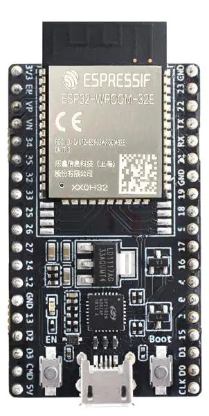
ESP32
The ESP32 is an affordable microcontroller with Wi-Fi and Bluetooth, making it perfect for connecting devices wirelessly. It can work in temperatures from -40°C to +125°C and is mainly used in IoT projects, wearable devices, and mobile gadgets.
The ESP32 microcontroller has 48 pins, but not all of them are available on every development board.

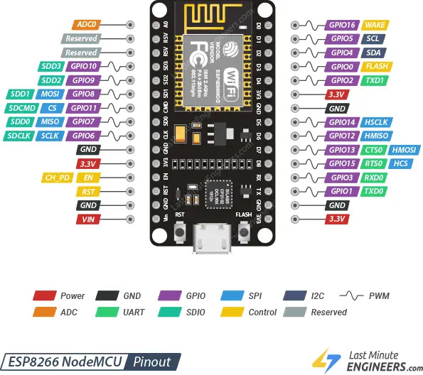
ESP866
The ESP8266 is an affordable microcontroller with built-in Wi-Fi, supporting Wi-Fi . However, it doesn't have Bluetooth, secure boot, flash encryption, or advanced security features like the ESP32.
The ESP8266 module has 32 pins, but the ESP8266 NodeMCU board only has 17 GPIO pins available for use.


Step by step guide
- Copy this URL
- http://arduino.esp8266.com/stable/package_esp8266com_index.json
- Install Arduino ide
- Go to file select preferences
- paste this URL
- Go to tools select board manager
- Search nodeMcu
- install nodeMcu
- then Go to board(Arduino uno) select NodeMcu 1.0(esp_12E module)
- Now ready to use(if port not showing then install ch340 and ch210x driver
How to connect Wi-Fi to Esp
#include <ESP8266WiFi.h>
const char* ssid = " ";
const char* password = "012345678";
void setup() {
Serial.begin(115200);
Serial.println("Connecting to WiFi...");
WiFi.begin(ssid, password);
while (WiFi.status() != WL_CONNECTED) {
delay(1000);
Serial.println("Connecting...");
Serial.println("Connected to WiFi!");
Serial.print("IP Address: ");
Serial.println(WiFi.localIP());
}
void loop() {
}
Control a led by IOT
- Go to Blynk website
- log in
- Create a new template
- Select microcontroller esp8266 and Done
- Go to DataStream
- select virtual pin
- write name , datatype - integer and done
- Go to Web Dashboard and drag & paste switch button
- click on setting of switch and select led(v0) ans Save
- install bynk on mobile if you want to control from mobile
- Go to +New device
- form template .
step 1 :- Create new template

step2 :- Go to Developer zone and select Home then click on DataStream

step3:- Create New DataStream

step 4:- Fill data as show below diagram

step 5:- Create more DataStream if required.

step 6- Create new Device

step 7:-After this process , You can get the template ID, name, and token. Copy all of these and paste them into your code. For example, if you're making a temperature monitoring system & need to copy this ID into your code.

Step 8 :-After all above process, you can see monting system in your desktop

How to connect ESP to blynk
#define BLYNK_TEMPLATE_ID "TMPL3_9RSWVB-"
#define BLYNK_TEMPLATE_NAME "Quickstart Template"
#define BLYNK_AUTH_TOKEN "31uP-QbRQrM6D2Y-4fMswPIDgnR1dZGA"
/* Comment this out to disable prints and save space */
#define BLYNK_PRINT Serial
#include <ESP8266WiFi.h>
#include <BlynkSimpleEsp8266.h>
char ssid[] = "Devd";
char pass[] = "012345678";
BLYNK_WRITE(V0)
{
int value=param.asInt(); //param is varible , as int mean store as integer .
Serial.println(value);
if(value ==1)
{
Serial.println("On");
digitalWrite(D7,HIGH);
}
if(value ==0)
{
Serial.println("OFF");
digitalWrite(D7,LOW);
}
}
void setup()
{
Serial.begin(115200);
Blynk.begin(BLYNK_AUTH_TOKEN, ssid, pass);
pinMode(D7,OUTPUT);
}
void loop()
{
Blynk.run();
}
1 LEDs
#define BLYNK_TEMPLATE_ID "TMPL3ZoMND65v"
#define BLYNK_TEMPLATE_NAME "4 led control"
#define BLYNK_AUTH_TOKEN "HDLM1IC5DdXpMaUFSZQRU80qOijnUGfH"
#define BLYNK_PRINT Serial
#include <ESP8266WiFi.h>
#include <BlynkSimpleEsp8266.h>
char ssid[] = "UNTOLD STORIES - LIBRARY";
char pass[] = "Password123";
BLYNK_WRITE(V0)
{
int value=param.asInt();
Serial.println(value);
if(value ==1)
{
Serial.println("On");
digitalWrite(D2,HIGH);
}
if(value ==0)
{
Serial.println("OFF");
digitalWrite(D2,LOW);
}
}
BLYNK_WRITE(V1)
{
int value=param.asInt();
Serial.println(value);
if(value ==1)
{
Serial.println("On");
digitalWrite(D1,HIGH);
}
if(value ==0)
{
Serial.println("OFF");
digitalWrite(D1,LOW);
}
}
void setup()
{
Serial.begin(115200);
Blynk.begin(BLYNK_AUTH_TOKEN, ssid, pass);
pinMode(D2,OUTPUT);
}
void loop()
{
Blynk.run();
}
2 LEDs
#define BLYNK_TEMPLATE_ID "TMPL3ZoMND65v"
#define BLYNK_TEMPLATE_NAME "4 led control"
#define BLYNK_AUTH_TOKEN "HDLM1IC5DdXpMaUFSZQRU80qOijnUGfH"
#define BLYNK_PRINT Serial
#include <ESP8266WiFi.h>
#include <BlynkSimpleEsp8266.h>
char ssid[] = "UNTOLD STORIES - LIBRARY";
char pass[] = "Password123";
BLYNK_WRITE(V0)
{
int value=param.asInt();
Serial.println(value);
if(value ==1)
{
Serial.println("On");
digitalWrite(D2,HIGH);
}
if(value ==0)
{
Serial.println("OFF");
digitalWrite(D2,LOW);
}
}
BLYNK_WRITE(V1)
{
int value=param.asInt();
Serial.println(value);
if(value ==1)
{
Serial.println("On");
digitalWrite(D1,HIGH);
}
if(value ==0)
{
Serial.println("OFF");
digitalWrite(D1,LOW);
}
}
BLYNK_WRITE(V2)
{
int value=param.asInt();
Serial.println(value);
if(value ==1)
{
Serial.println("On");
digitalWrite(D3,HIGH);
}
if(value ==0)
{
Serial.println("OFF");
digitalWrite(D3,LOW);
}
}
void setup()
{
Serial.begin(115200);
Blynk.begin(BLYNK_AUTH_TOKEN, ssid, pass);
pinMode(D2,OUTPUT);
pinMode(D1,OUTPUT);
pinMode(D3,OUTPUT);
}
void loop()
{
Blynk.run();
}
IR SENSOR
#define BLYNK_TEMPLATE_ID "TMPL3NFPp8wdS"
#define BLYNK_TEMPLATE_NAME "IR sensor"
#define BLYNK_AUTH_TOKEN "Zt9OrbpSaYTz63WHvCBZlV4vvhuG73nL"
#define BLYNK_PRINT Serial
#include <ESP8266WiFi.h>
#include <BlynkSimpleEsp8266.h>
// Replace with your Blynk Auth Token, WiFi credentials
char ssid[] = "UNTOLD STORIES - LIBRARY"; // Your Wi-Fi SSID
char pass[] = "Password123"; // Your Wi-Fi password
// Pin connected to the IR sensor OUT pin
int irPin = D2; // IR sensor connected to D2 (GPIO4)
BlynkTimer timer;
void setup() {
// Start the Serial Monitor
Serial.begin(115200);
// Connect to Wi-Fi
Blynk.begin(BLYNK_AUTH_TOKEN, ssid, pass);
// Set IR sensor pin as input
pinMode(irPin, INPUT);
// Display connection status
Serial.println("Connecting to WiFi...");
}
void loop() {
// Read the IR sensor data (HIGH = object detected, LOW = no object)
int irValue = digitalRead(irPin);
// Send the IR sensor data to the Blynk app via virtual pin (V1)
Blynk.virtualWrite(V1, irValue); // V1 is the virtual pin for the IR sensor
// Print sensor status on the Serial Monitor (optional)
if (irValue == LOW) {
Serial.println("Object detected!");
} else {
Serial.println("No object detected.");
}
// Run Blynk
Blynk.run();
// Wait a bit before taking the next reading
delay(1000); // Adjust the delay as needed
}
Ultrasonic
#define BLYNK_TEMPLATE_ID "TMPL3K99K8lbF"// set your id , name and token
#define BLYNK_TEMPLATE_NAME "utrasonic2"
#define BLYNK_AUTH_TOKEN "mVwStcWPvA5xJHnp_GHzttDFPhs4wkCZ"
#include <ESP8266WiFi.h>
#include <BlynkSimpleEsp8266.h>
//char auth[] = "Your_Blynk_Auth_Token"; // Your Blynk auth token
char ssid[] = "UNTOLD STORIES - LIBRARY"; // Your Wi-Fi SSID
char pass[] = "Password123"; // Your Wi-Fi password
// Define the pins for the ultrasonic sensor
#define TRIG_PIN D1
#define ECHO_PIN D2
long duration;
int distance;
void setup() {
// Start serial communication
Serial.begin(9600);
// Set the ultrasonic sensor pins
pinMode(TRIG_PIN, OUTPUT);
pinMode(ECHO_PIN, INPUT);
// Connect to Wi-Fi
Blynk.begin(BLYNK_AUTH_TOKEN, ssid, pass);
// Set the trigger pin low initially
digitalWrite(TRIG_PIN, LOW);
}
void loop() {
// Trigger the ultrasonic sensor
digitalWrite(TRIG_PIN, HIGH);
delayMicroseconds(10);
digitalWrite(TRIG_PIN, LOW);
// Measure the time for the echo to return
duration = pulseIn(ECHO_PIN, HIGH);
// Calculate the distance in cm
distance = duration * 0.0344 / 2;
// Send distance to the Blynk app
Blynk.virtualWrite(V1, distance); // Send distance to virtual pin V1
// Print distance to serial monitor
Serial.print("Distance: ");
Serial.print(distance);
Serial.println(" cm");
// Wait for a while before the next reading
delay(1000);
// Run Blynk
Blynk.run();
}
Temp and Humidity(by Blynk)
#define BLYNK_TEMPLATE_ID "TMPL3vydE8QcY"
#define BLYNK_TEMPLATE_NAME "Temp and humidity"
#define BLYNK_AUTH_TOKEN "9FYJRp4RaN3h-wliX7daELKLKes4nYWD" //9FYJRp4RaN3h-wliX7daELKLKes4nYWD
#include <ESP8266WiFi.h>
#include <BlynkSimpleEsp8266.h>
#include <DHT.h>
//#include <ThingSpeak.h> optional if you use ThingSpeak too
char ssid[] = "My Wi-Fi";
char pass[] = "My password";
// ThingSpeak credentials
//unsigned long channelID = Your_ThingSpeak_Channel_ID; // optional if you use ThingSpeak
//const char *apiKey = "Your_ThingSpeak_Write_API_Key";
// DHT11 sensor pin
#define DHTPIN D2
#define DHTTYPE DHT11
DHT dht(DHTPIN, DHTTYPE);
WiFiClient client;
void setup() {
// Start serial communication
Serial.begin(9600);
Blynk.begin(BLYNK_AUTH_TOKEN, ssid, pass);
dht.begin();
}
void loop() {
float temperature = dht.readTemperature();
float humidity = dht.readHumidity();
// Check if the readings failed
if (isnan(temperature) || isnan(humidity)) {
Serial.println("Failed to read from DHT sensor!");
return;
}
Serial.print("Temperature: ");
Serial.print(temperature);
Serial.print(" °C ");
Serial.print("Humidity: ");
Serial.print(humidity);
Serial.println(" %");
Blynk.virtualWrite(V1, temperature); // Virtual pin V1 for temperature
Blynk.virtualWrite(V2, humidity); // Virtual pin V2 for humidity
//ThingSpeak.setField(1, temperature); // Field 1 for temperature
// ThingSpeak.setField(2, humidity); // Field 2 for humidity
//ThingSpeak.writeFields(channelID, apiKey); // Write the data to ThingSpeak
Blynk.run();
// Wait 10 seconds before the next reading
delay(10000);
}
Temp and Humidity
We are going to use ThingSpeak for print graph of temp and humidity on desktop.
#include <ESP8266WiFi.h>
#include <ThingSpeak.h>
#include <DHT.h>
// Define pin numbers
#define DHTPIN D2 // Pin for DHT sensor (e.g., D4 or GPIO2)
#define DHTTYPE DHT11
// #define FIREPIN A0
const char *ssid = "Dev D"; // put your Wi-Fi name
const char *password = "Password123"; // put your Wi-Fi password
unsigned long channelNumber = 2880065; // ThingSpeak Channel Number
const char *writeAPIKey = "16QWX07Z90EC59J8"; // ThingSpeak API key
WiFiClient client; // Wi-Fi client to connect to ThingSpeak
//ThingSpeakServer thingSpeakServer; // ThingSpeak server object
DHT dht(DHTPIN, DHTTYPE); // Initialize the DHT sensor
void setup() {
Serial.begin(115200);
WiFi.begin(ssid, password);
while (WiFi.status() != WL_CONNECTED) {
delay(1000);
Serial.println("Connecting to WiFi...");
}
Serial.println("Connected to WiFi");
ThingSpeak.begin(client); // Initialize ThingSpeak
dht.begin(); // Initialize DHT sensor
}
void loop() {
// Read Temperature and Humidity
float humidity = dht.readHumidity();
float temperature = dht.readTemperature();
// Read Fire Sensor (MQ-2/MQ-3)
int fireValue = analogRead(FIREPIN); // Fire sensor output
// Print sensor values to Serial Monitor for debugging
Serial.print("Temperature: ");
Serial.print(temperature);
Serial.print(" C, Humidity: ");
Serial.print(humidity);
Serial.print("%, Fire Sensor: ");
Serial.println(fireValue);
// Upload the sensor data to ThingSpeak
ThingSpeak.setField(1, temperature);
ThingSpeak.setField(2, humidity);
ThingSpeak.setField(3, fireValue);
// Write data to ThingSpeak
ThingSpeak.writeFields(channelNumber, writeAPIKey);
// Wait 20 seconds before uploading new data
delay(20000);
}
Image recognition Image recognition using the AI Thinker ESP32-CAM means using the ESP32-CAM board to take pictures with its camera and then use smart computer programs (AI) to identify or detect things in those pictures. The ESP32-CAM is a small device that has an ESP32 chip (which lets it connect to Wi-Fi and Bluetooth) and a camera module (called OV2640) to take photos or videos. You can use this board to recognize faces, objects, or other things in images, making it useful for tasks like security, monitoring, or smart devices.

For making this project you have to use
Hardware
bread board
some jumper wires
Software
Arduino ide
Edge impulse website
There are following steps for making this project in below
Step 1:- open Arduino ide on desktop then go file then select preference and copy below link and paste
https://dl.espressif.com/dl/package_esp32_index.json
Step 2:- Go to tools and select manage library and search bar, type ESP32 and click on Install for the esp32 package by Espressif Systems.
Step 3:- Go to Tools then Board and select AI Thinker ESP32-CAM
Step 4:- Go to tools and select manage library and search eloquent and install


or
#define WIFI_SSID "SSID"
#define WIFI_PASS "PASSWORD"
#define HOSTNAME "esp32cam"
#include <eloquent_esp32cam.h>
#include <eloquent_esp32cam/extra/esp32/wifi/sta.h>
#include <eloquent_esp32cam/viz/image_collection.h>
using eloq::camera;
using eloq::wifi;
using eloq::viz::collectionServer;
void setup() {
delay(3000);
Serial.begin(115200);
Serial.println("___IMAGE COLLECTION SERVER___");
// camera settings
// replace with your own model!
camera.pinout.ai thinker();
camera.brownout.disable();
// Edge Impulse models work on square images
// face resolution is 240x240
camera.resolution.face();
camera.quality.high();
// init camera
while (!camera.begin().isOk())
Serial.println(camera.exception.toString());
// connect to WiFi
while (!wifi.connect().isOk())
Serial.println(wifi.exception.toString());
// init face detection http server
while (!collectionServer.begin().isOk())
Serial.println(collectionServer.exception.toString());
Serial.println("Camera OK");
Serial.println("WiFi OK");
Serial.println("Image Collection Server OK");
Serial.println(collectionServer.address());
}
void loop() {
}
code and paste in google you can see your esp camera monitor .
Step 7:- Go to google and search edge impulse , visit that website and sign In.
Step 7:- Go to google and search edge impulse , visit that website and sign In.

Step 9:- Go to edge impulse and click on ( + Add data)and select all data o which you have downloaded then save .
Step 10:-Click on New label > Write Mango > save label
Step 11:-Click on New label > Write Orange > save label
Step 12:- Impulse design > create impulse > image widths > image height > 96
Step 13:- Add processing block > click on learning block > Add > click on image > color > arragecole > then save
Step 14 :- Go to object detection > learning rate > 0.01 > start training
Step 15 :- Go to development > Arduino > click on change target > select ESP.
Step 16:- after set target device then download zip file.
Step 17:- Go to tools > include library > add zip (ex- fruit recognition)
Step 18:- Go to example (Arduino) and select > esp camp.
Step 19:- Enable AI thinker in code and disable ESP EYE .
Step 20:- Upload this code in Esp camp , Now your project complete.
How to connect multi sensor to esp.
#define BLYNK_TEMPLATE_ID "TMPL3fAdqULSf"
#define BLYNK_TEMPLATE_NAME "RAIN DROP SENSOR"
#define BLYNK_AUTH_TOKEN "JDRzuFme5J7Ty97KaYgVqpLNTneltrIU"
#define BLYNK_PRINT Serial
#include <ESP8266WiFi.h>
#include <BlynkSimpleEsp8266.h>
// Replace with your Blynk Auth Token, WiFi credentials
char ssid[] = "UNTOLD STORIES - LIBRARY"; // Your Wi-Fi SSID
char pass[] = "Password123"; // Your Wi-Fi password
// Pin connected to the IR sensor OUT pin
int RainPin = A0; // IR sensor connected to D2 (GPIO4)
int IRPin = D0;
int LDRPin = D2;
BlynkTimer timer;
void setup() {
// Start the Serial Monitor
Serial.begin(115200);
// Connect to Wi-Fi
Blynk.begin(BLYNK_AUTH_TOKEN, ssid, pass);
// Set IR sensor pin as input
pinMode(RainPin, INPUT);
pinMode(IRPin, INPUT);
pinMode(LDRPin, INPUT);
// Display connection status
Serial.println("Connecting to WiFi...");
}
void loop() {
// Read the IR sensor data (HIGH = object detected, LOW = no object)
int RainValue = analogRead(RainPin);
int IRValue = analogRead(IRPin);
int LDRValue = analogRead(LDRPin);
// Send the IR sensor data to the Blynk app via virtual pin (V1)
Blynk.virtualWrite(V0, RainValue); // V1 is the virtual pin for the IR sensor
Blynk.virtualWrite(V1, IRValue);
Blynk.virtualWrite(V2, LDRValue);
Blynk.run();
delay(50);
Serial.println("Rain value");
Serial.print(RainValue);
Serial.println("IR value");
Serial.print(IRValue);
Serial.println("LDR value");
Serial.print(LDRValue);
}
IR SENSOR WITH VIRTUAL BUZZER.
#define BLYNK_TEMPLATE_ID "YOUR_TEMPLATE_ID"
#define BLYNK_DEVICE_NAME "IR Sensor Alarm"
#define BLYNK_AUTH_TOKEN "YOUR_BLYNK_AUTH_TOKEN"
#include <ESP8266WiFi.h>
#include <BlynkSimpleEsp8266.h>
char auth[] = BLYNK_AUTH_TOKEN;
char ssid[] = "YOUR_WIFI_SSID"; // WiFi naam
char pass[] = "YOUR_WIFI_PASSWORD"; // WiFi password
#define IR_SENSOR D5 // IR sensor output pin
void setup() {
Serial.begin(115200);
pinMode(IR_SENSOR, INPUT);
Blynk.begin(auth, ssid, pass);
}
void loop() {
Blynk.run();
int irValue = digitalRead(IR_SENSOR);
if (irValue == LOW) {
// Object detected
Blynk.virtualWrite(V1, 1); // Virtual buzzer ON (Blynk app)
} else {
Blynk.virtualWrite(V1, 0); // Virtual buzzer OFF
}
}
IR WITH SERVO
#define BLYNK_TEMPLATE_ID "YOUR_TEMPLATE_ID"
#define BLYNK_DEVICE_NAME "IR Sensor Alarm"
#define BLYNK_AUTH_TOKEN "YOUR_BLYNK_AUTH_TOKEN"
#include <ESP8266WiFi.h>
#include <BlynkSimpleEsp8266.h>
char auth[] = BLYNK_AUTH_TOKEN;
char ssid[] = "YOUR_WIFI_SSID"; // WiFi naam
char pass[] = "YOUR_WIFI_PASSWORD"; // WiFi password
#define IR_SENSOR D5 // IR sensor output pin
void setup() {
Serial.begin(115200);
pinMode(IR_SENSOR, INPUT);
Blynk.begin(auth, ssid, pass);
}
void loop() {
Blynk.run();
int irValue = digitalRead(IR_SENSOR);
if (irValue == LOW) {
// Object detected
Blynk.virtualWrite(V1, 1); // Virtual buzzer ON (Blynk app)
} else {
Blynk.virtualWrite(V1, 0); // Virtual buzzer OFF
}
}
How to control motor by esp
#define BLYNK_PRINT Serial
#include <ESP8266WiFi.h>
#include <BlynkSimpleEsp8266.h>
// Replace with your Auth Token
char auth[] = "YourAuthToken";
// Replace with your WiFi credentials
char ssid[] = "YourWiFiSSID";
char pass[] = "YourWiFiPassword";
// Motor control pin
int motorPin = D1; // GPIO5
void setup()
{
Serial.begin(9600);
pinMode(motorPin, OUTPUT);
digitalWrite(motorPin, LOW); // Motor off
Blynk.begin(auth, ssid, pass);
}
BLYNK_WRITE(V0) // When button on V0 is pressed
{
int value = param.asInt(); // 1 or 0
digitalWrite(motorPin, value);
}
void loop()
{
Blynk.run();
}
I2C connect with LCD
https://github.com/fdebrabander/Arduino-LiquidCrystal-I2C-library.git
1 step -liquid crystal i2c library zip file download
2nd step -
Connections (I2C LCD ↔ Arduino):
-
VCC → 5V (powers LCD)
-
GND → GND (common ground)
-
SDA → A4 (I2C data line on Uno/Nano)
-
SCL → A5 (I2C clock line on Uno/Nano)
NodeMCU (ESP8266):
-
SDA = D2 (GPIO4)
-
SCL = D1 (GPIO5)
Code for scan LCD code -
#include <Wire.h>
void setup() {
Wire.begin();
Serial.begin(9600);
Serial.println("\nI2C Scanner");
}
void loop() {
byte error, address;
int nDevices;
Serial.println("Scanning...");
nDevices = 0;
for (address = 1; address < 127; address++) {
Wire.beginTransmission(address);
error = Wire.endTransmission();
if (error == 0) {
Serial.print("I2C device found at address 0x");
if (address < 16) Serial.print("0");
Serial.print(address, HEX);
Serial.println(" !");
nDevices++;
} else if (error == 4) {
Serial.print("Unknown error at address 0x");
if (address < 16) Serial.print("0");
Serial.println(address, HEX);
}
}
if (nDevices == 0)
Serial.println("No I2C devices found\n");
else
Serial.println("done\n");
delay(5000); // wait 5 seconds before next scan
}
Code for 'Hello World"for Arduino
#include <Wire.h>
#include <LiquidCrystal_I2C.h>
// If your I2C address is 0x27 or 0x3F, update here
LiquidCrystal_I2C lcd(0x27 , 16, 2);
void setup() {
lcd.begin(16, 2); // Initialize with 16 columns and 2 rows
lcd.backlight(); // Turn on the backlight
lcd.setCursor(0, 0);
lcd.print("I win!");
lcd.setCursor(0, 1);
lcd.print("I2C LCD Test");
}
void loop() {
}


Comments
Post a Comment